Table of Contents
Hello, Friends today we will study the signals used in plc (programmable logic controller, which is an electronic device that is used in industry for automatic operation. Today in this blog we learn about the Analog Input and output signal. So Let’s get start
PLC Signals (Analog Input and Analog Output) : Introduction
We heard about Digital Input and Output, where the values get in “1” or “0” means On or OFF, but if we talk about the PLC Analog Input and Output signals, this is different.
In Analog Input we are getting the continuous value. Example:- A Temperature sensor gives the continuous analog value, which means the temperature is changing continuously, this happens because if the temperature sensor changes the value, then the temperature is calibrated according to the set value. Like example:
0 ohm = 0 degree Celsius
5 ohm = 5 degree Celsius …. And so on
So in this value is changing continuously….
In Analog Output, we generate values for a certain range in the form of voltage and current. Example:- I would like to modulate the cooling valve then we have to give a signal as per the requirement…. If we take a signal in the Voltage form (0 – 10 V Dc) then the valve will move accordingly.
For example : 0 Volt Dc = 0 % move
2 Volt Dc = 20% move
10 Volt Dc = 100% move
In this way, the output signal we are getting and the field devices are working.
PLC Analog Input Configuration
Now we will know how to do the input configuration with the above topic PLC Analog Input and Output Signals
Connect Analog Sensor: – First, we must connect the analog sensor to the controller and configure according to the set value of voltage or current.
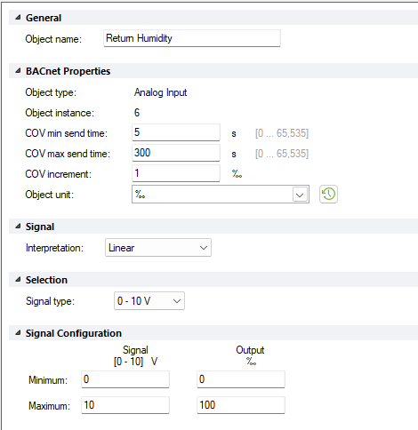
Fig:- Analog Input Block of Program
We can see above that Analog Input block, where Humidity Sensor is connected, and the configuration is done according to the Configuration Manual and Model Number. In this Minimum voltage is “0” so the output is zero and if the input signal increases up to 10 v (higher limit DC voltage) so the 100% Humidity will come.
- Setting the Parameter: – you see in the above image that the parameter is settled as the percentage of Humidity will show.
- Signal Condition: – So, in the Humidity block as the signal come it will react accordingly, as the program is configured.
- Data Log: – The data we are getting from the sensor is saved in the memory for further action and the analysis can be done.
- Condition operation: – with the input data we can control and maintain temperature or any other parameter as per the demand.
PLC Analog Output Configuration
Now let us know how to do the Output Configuration of the Analog.
Connect Output device:- In the output side, field
device is connected, these are operated as per the logic given to the program,
also the input side the signal is coming and with the help of it the device is
being run. PLC Analog Input and Output Signals
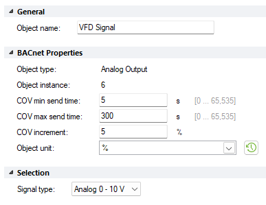
Set Scaling Parameters: – Parameter is being set for the operation as seen in the above image, the signal type, where Analog 0 -10 v is set, so the output is come in DC volt and the VFD is working according to the signal provided. So PLC Analog Input and Output Signals where scaling is important.
Define the Control Logic : – For generating the output signal we have to define the control logic as per the instruction, so PLC Analog Input and Output Signals are connected as below

Fig : – FBD of AHU Operation program
In the above block you can see the PLC Analog Input and Output Signal, in the input side the Temperature set point is given as 10 Degree, as the Return Temp. is 23.88 Degree and the Fan status is On, so as per the Logic the Colling Valve (the Output device) with act and open 100 % as the Return temp. is high as compare to the set point. Also the Output Signal will work in Analog voltage from 0 to 10V.
Safety Considerations : -In Every Logic we have think about the safety, so in the block image you can see in the PID loop where Supply status of Fan is coming, that means when supply status will not come then further operation will not execute and cooling valve will not activate. So PLC Analog Input and Output Signals will not work accordingly.
Use of PLC Analog Input and Output Signal Configuration in the Program
Now we will see via Function Block Diagram, how to use the plc Analog Input and the Output Block in the program for the calibration of the Field devices
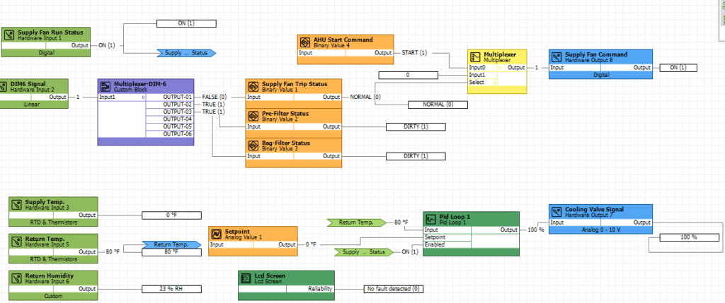
Fig: – FBD of CAV AHU Program
In the above block you can see different Inputs and output in the program where the Binary values also come in o and 1, the RTD values of temperature sensor come, the PID loop where the output is given to the cooling valve, which will operate according to the the set point. When the start commend is given to the AHU then it will see the Trip command that that any trip command is coming or not, when every thing is Normal the further the On command is passed through the Multiplexer and the AHU (Air Handling Unit) Start.
Also the Binary command is coming for the Pre Filter rand the Bag Filter, where the value is in the 0 and 1, so the attribute is set as the Clean and the Dirty, these are connected with the Dim Signal.
Same with Supply Fan Run status, this is also the Digital Signal where the signal is getting in the 0 and 1. Which is set as 0 for Off and 1 for On, with the help of this the PID loop is set, so this is the double confirmation that the supply fan is ON and further the Valve will operate.
we are reading the Article on PLC Analog Input and Output Signals in the DTC Cabinet
Some of the operation done with the Signal are: –
- Temperature Control
- Speed control of motor via VFD
- Pressure measurement
- Differential pressure measurement
- Static pressure measurement
- Flow measurement
we have study PLC Analog Input and Output Signals configuration in detail
Analog Input Signal with 2 wire , 3 wire and 4 wire
2 wire analog signal

In the above diagram we can see the 2 wire analog signal, where the A+ and A_in is connected with the signal 4 – 20 mA, there is the two loop one is the signal and the other is the power loop.
With the signal loop the signal is coming in the milli ampere.
3 wire analog signal
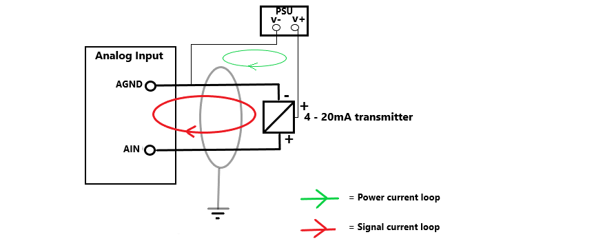
In the 3 wire analog signal we can see that there is two loop the signal loop and the power loop, also the connection is done with the PSU, the negative is connected with the A Gnd and the positive is connected with the Ain.
4 wire analog signal
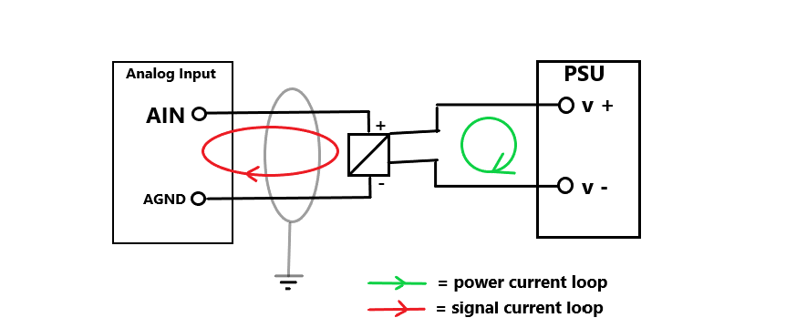
As seen in the figure there is 4 wire with the analog unit and the PSU unit, where the power current loop and the signal current Is shown.
In the above article PLC Analog Input and Output Signals we discuss in details
